Imagine you want to build something. You’d probably start by using a pencil and paper to draw a design of what you are trying to build. You may use a tape measure to calculate the proportions, and then use you hands to craft this.
Well, I do something similar, but I use computers and computer-controlled equipment to provide these functions.
First I use a process called CAD (Computer-Aided Design)
I sit down with a computer, and instead of drawing the item by hand, I use special software to design it on the screen. The software helps me create a detailed, precise plan for the item. I can see it from every angle, and if I make a mistake or want to change something, it’s easy to adjust—like erasing and redrawing but much quicker and more accurate.
For Example:
I wanted to build a working Flight Control Unit for an Airbus A320 Flight Simulator program.
Here’s what one looks like.
In the real Airbus, there are many switches that can light up to indicate various statuses and warnings. They are called Korry Switches and are brand names of the Korry Electronics company.
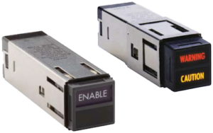
In my simulator model, I wanted to replicate the look and function of these switches because the real Korry switches cost over $2,000 each.
Real Korry switches are based on 12v and 24v, and have push-pull and lock capabilities as well as LED lighting.
For them to work in the simulator they had to work on either 3.3 or 5 volts, which is the limitation of the CPU I have chosen. so I had to design and build my own.
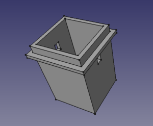
Using CAD Software I designed the components needed, first the outer slide of the Korry switch, which would be used to hold a tactile switch, and the inner slide.
The component had to be designed to ensure the inner slide would move freely in and out allowing the slide to activate the tactile switch upon pressing.
Depending upon the function of the switch I would be using either a momentary press tactile switch or a latching one.
Holes had to be designed into the model to allow the leads from the tactile switch to protrude for connection to the circuit board. It also had to be designed such that leads from the LEDs, which would sit in the inner slide could also be connected.
Lastly, a lock mechanism had to be designed to prevent the inner slide from falling out.

This needed two compartments for LEDs to be inserted.
Real Korry Switches frequently have multiple indicators, so being able to light up one or the other sides of the switch, or both sides simultaneously was a must.
Obviously a light-blocking wall had to be designed to prevent light bleed from one LED to the other.
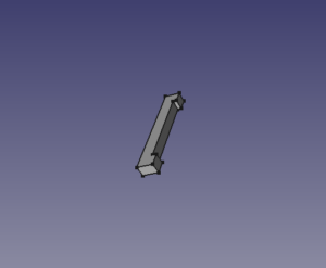
In addition, the locking mechanism designed for the outer slide above had to be designed into the inner slide as well.
This turned out to be just a simple tapered rod that went through both the outer and inner slides at the right height.
This allows both the press operation of the inner slide and tactile switch and offers no interference with the LEDs.
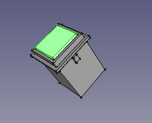
I then ran the assembly function of the CAD software to make sure everything fit.
As you can see from this image, taken from the CAD software, the assembled components provide a reasonable facsimile of the original Korry-type switch.
Once I was happy with the design I used the computer to create clear instructions in machine code and sent them to a machine.
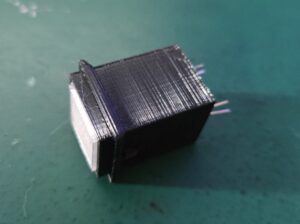
This type of computer-aided manufacturing relies on the principle of taking an original block of material and milling and drilling out the design.
Because CNC milling would have led to too much waste, I instead chose to print the components on a 3D printer.
Developing products this was is like having a very skilled craftsman who follows the blueprint exactly, but the machines do all the hard, repetitive work much faster and with a high degree of precision.
In short:
- CAD is the computer’s way of helping me create a detailed design, just like a very precise blueprint.
- CAM is the computer telling a machine how to make that design into a real, physical object.
The whole process makes it easier, faster, and more accurate to create all sorts of products—whether it’s furniture, cars, or even aeroplanes—by combining my ideas with the power of modern technology.
Sharing the love
As I have shown, CAD/CAM is a way of producing products where I can, simultaneously, emulate a designer, draftperson and production engineer.
Then I thought, what about other “stuff” that people might want, that I could develop and produce?
CNC machines and 3D Printers are coming down in price, but for a one-off project, nobody would want to spend around $500-$1000 for a machine, invest in the software and training to use it, when all they wanted was a small product.
I searched for companies that provide bespoke manufacturing and found the set-up costs and manufacturing increased the prices of one-off work to a level that was really untenable.
So I asked around my friends to see if my services would be of use. I figured, if they wanted something, perhaps there was a chance other people wanted the same thing too.
I offer the design free of charge, and a small cost for production, on the basis that I would own the rights for future production of the items they needed.
That way, I could provide a cheaper runoff cost for them, and at the same time increase my catalogue of products I can produce for other people.
This is how I’ve come up with the catalogue of products below, at a price that won’t break the bank.
3D Printed Catalogue
Each of the items in my catalogue of designs may be offered in different formats.
All the designs are offered in physical format, and the prices are subject to packaging and shipping costs, which are determined at checkout.
Some of the designs are also offered in electronic formats, with the raw design files or the machine code files for the method of production or both.
These electronic files are offered under a Creative Commons licenses.
Raw files are issued under the CC-BY-SA license.
This license enables reusers to distribute, remix, adapt, and build upon the material in any medium or format, so long as attribution is given to the creator. The license allows for commercial use. If you remix, adapt, or build upon the material, you must license the modified material under identical terms. The full terms of the CC BY-SA license can be found here, it includes the following elements:
BY: credit must be given to the creator.
SA: Adaptations must be shared under the same terms.
Machine Code files are issued under the CC BY-NC-SA license.
This license enables reusers to distribute, remix, adapt, and build upon the material in any medium or format for noncommercial purposes only, and only so long as attribution is given to the creator. If you remix, adapt, or build upon the material, you must license the modified material under identical terms. The full terms of the CC BY-NC-SA license can be found here, it includes the following elements:
BY: credit must be given to the creator.
NC: Only noncommercial uses of the work are permitted.
SA: Adaptations must be shared under the same terms.

